
Basics of Mechanical Design and Solidworks
(2015 - present)
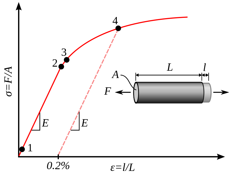
Mechanics of Materials
strength, stiffness, elasticity
Stiffness and strength often get confused. Often times when we say we want something strong we really want it to be stiff. Strength is the maximum load a material can take before failing. Stiffness is the amount a given shape will deflect, when made out of a given material. Of course we want strength too, but technically they are different. The strength to weight ratio and stiffness to weight ratio can be different. Strength/Strain
Loading stiffness: transverse, axial, buckling
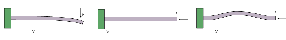
Stiffness is dependent on not just the inherent material elasticity, but also its shape. This gives the designer more flexibility in design. That is, you can choose the material you'd like to use, and then through geometry you can change its effective stiffness. Depending on your loading conditions you may choose a high strength material and from there adjust your geometry to maximize stiffness. The images above show transverse, axial, and buckling loading conditions. The equations below show how axial stiffness is dependent only on cross-sectional area, while bending and is dependent
Axial loading stiffness, $k_{a}$, transverse loading stiffness, $k_{b}$:
$$\begin{align} k_{a} &= \frac{ AE }{ L } & &= \frac{\pi E}{4} \left( \frac{d^{2}}{L} \right) \\
k_{b} &= \frac{ 3EI }{ L^{3} } & &= \frac{3\pi E}{64} \left( \frac{d^{2}}{L} \right)^{2} \frac{1}{L} \end{align}$$
It can be seen that axial stiffness is related to a beam slenderness ratio $ \frac{d^{2}}{L} $ by an order of magnitude scaling $O( \frac{ d^{2} }{L} ) = O( 1 )$. The bending stiffness of the same beam is then a two order of magnitude $O( 2 )$ scaling of this slenderness ratio, and additionally, inversely proportional to the length of the beam.
There is a limit to the allowable slenderness ratio, and that limit is due to buckling. A long slender beam will still exhibit bending modes even in an axial load condition when the compression stress reaches a critical stress. The Euler buckling criteria for a slender beam in compression is \cite{Hibbeler2011}: \begin{align} \sigma_{cr} &= \frac{ P_{cr} }{ A_{cr} } = \frac{\pi^{2}E}{ \left( \frac{L_{e}}{r} \right)^{2} } \\ r &= \sqrt{ \frac{I}{A} } \end{align} where, $r$ is the radius of gyration, $\sigma_{cr}$ is the critical buckling stress, $I$ second area moment of inertia, $A$ projected area of beam, $E$ modulus of elasticity, and $L_{e}$ is the effective length. The effective length is dependent on the constraints applied to the end conditions and can be found in the references of Hibbeler or Juvinall \cite{Hibbeler2011, Juvinall1999} or any other mechanics textbook. Maybe an easier way to look at the equation is in the form with $r$ explicit $$\begin{align} \sigma_{cr} &= \frac{\pi^{2}E I}{ L_{e}^{2}A } \end{align}.$$ Here we see that just increasing the area can actually lower the buckling strength, while increasing material stiffness or second area moment of inertia increases our buckling strength.
Second Area Moment of Inertia - $I$
The second area moment of inertia, $I$, is the single most misunderstood and important part of mechanical design. $I$ is shape dependent, not material dependent, and it is essentially quartic.
For a round rod, I, is give below.
Second Area Moment of Inertia - Wikipedia
List of Area Moments

What we see is that by increasing $r$ a little bit we get a quartic increase in bending stiffness and a quadratic increase in effective buckling length. So $I$ is a big knob that can be turned to tune in your design to hit your requirements. It's also important to look at as a way to increase stiffness while not increasing mass, as much.
Force and Torque, or Stress and Moments
\begin{align} F &= ma \\ \tau &= Fr \\ \sigma &= \frac{F}{A} \\ M &= r \times F \end{align}
Machine Components
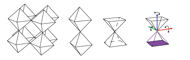
Kinematic Constraints
There are six degrees of freedom in the physical world. Translation in $x, y, z$ and rotation about each of those axes. We all know, for ever action there is an equal and opposite reaction. That means there is a reaction force for any force applied, and a force is necessary to cause action or motion.
Constraint means to rigidly prevent motion along any one of these degrees of freedom, such that if a force is applied the object is rigidly held along the line of action of the constraint.
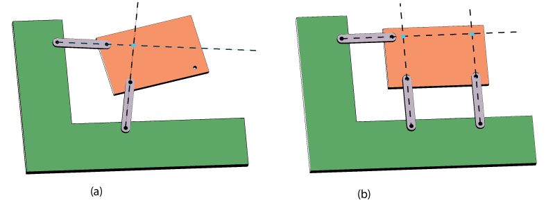
Mechanisms
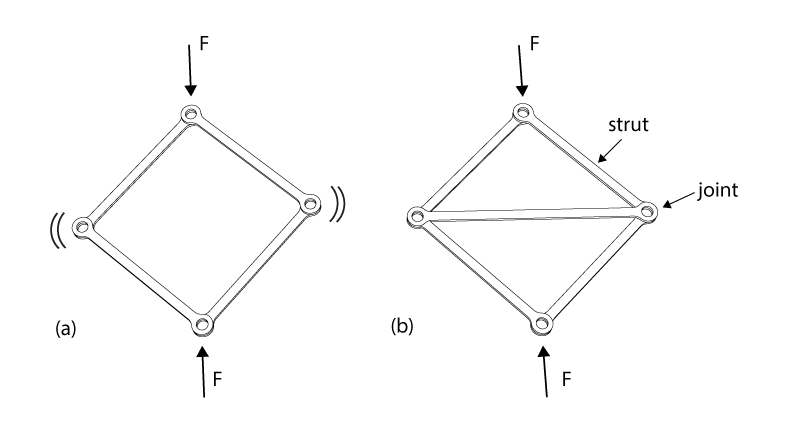
A mechanism is the result of an object not beign fully constrained. We can see that in (a) in the figure above we have two lines of contact that intersect at a point. This point is an instantaneous center of rotation. That means, for small disturbances the object rotates about that point. This exists because we have a line of action acting mostly in the x direction and one acting mostly in the y direction. But there is nothign preventing rotation about the z axis which points out of the page. The (b) image shows a third constraint, that is also acting in the y-direction, preventing rotation about the z-axis.
Note, that the further away the second support is, the stiffer that rotation constraint becomes. If we look back at our equation for bending moment $M$ and torque, putting the second support some distance $r$ away from our instantaneous center of rotation we are effectively applying a reaction constraint torque that is scaled by $r$. The further away our constraints are from eachother the stiffer our structure. This is again, similar to putting material further away from the neutral axis creates a larger I and a stiffer structure.
The image below shows how using struts and pins we can make either a mechanism or a rigid body. This is the basis for how bridges are built, and my own research (discrete cellular lattices).
Linkages
Four-bar Linkages
Levers: \begin{align} \tau_{1} &= \tau_{2} \\
F_{1}r_{1} &= F_{2}r_{2} \\
F_{1} &= \frac{F_{2}r_{2}}{r_{1}}
\end{align}
Gears
Similar to levers, power in equals power out (neglecting efficiency losses due to friction). Below, $ P $ is power, $ w $ is angular velocity (i.e. rpm), $ N $ is number of teeth ~ radius, $ \tau $ is torque. : \begin{align} P_{1} &= P_{2} \\ w_{1} \tau_{1} &= w_{2} \tau_{2} \\ \tau_{1} &= \frac{w_{2}}{w_{1}} \tau_{2} \\ \end{align} Similarly, the speed of one gear to the next is related by the following. \begin{align} w_{1}N_{1} &= w_{2}N_{2} \\ \frac{w_{2}}{w_{1}} &= \frac{N_{1}}{N_{2}} \\ \end{align} Taking that and putting it together we get what we really care about: \begin{align} \tau_{1} &= \frac{N_{1}}{N_{2}} \tau_{2} \\ \tau_{2} &= \frac{N_{2}}{N_{1}} \tau_{1} \end{align} Output torque is the ratio of output teeth (or diameter) to input teeth (diameter) times the input torque. To get more torque and less speed you want small input gears and large output gears.
Gears, belts, cables, these are all the same relations of torque and speed as described in the last two equations, above.
Gears counter-rotate. They pretty much always have backlash. They are efficient.
Belts
Belts co-rotate. They can be used for timing. Can effectively remove backlash. Requires tensioning methods - must be tensioned to 57% rated load. There are minimum bend radiuses that must be observed for longevity/fatigue.
Cables
Cables co-rotate. Power can be transmitted around corners. Zero backlash. But there can be relaxation of the fibers. Must be tensioned to 57% rated load. There are minimum bend radiuses that must be observed for longevity/fatigue.
bearings and bushings
Used for reducing friction between two objects moving relative to one another. There is an inner and an outer race.
fasteners
Fasteners are useful. They allow you to take apart your assemblies. The first of whatever you design, I can pretty much guarantee, you will always have to put it together and take it apart at least a half dozen times before you're done. So, design so that you can do this, to fix things. Snaps are cute, but they're difficult to tune to correctly work and not snap off or plastically deform after even a couple of uses - they are very dependent on material elastic modulus.
Solidworks
The solidworks stuff must really be seen, reading words won't really make much sense.
Here is a link to a video someone made of the advanced master modeling class I ran in 2014 for how to make.
Good practices
- Name your dimensions
- Name your sketches and features
- Reference the most primitive objects - I prefer just one or two sketches and vertices/points in those sketches.
Tricks that aren't in tutorials
Link feature values
Equations
How to use them, they can be a headache sometimes.
Multi-body parts
Rapid prototyping. Make lots of parts without the trouble of making individual parts and inserting them into assemblies. Does not allow for simulating motions.
Surfaces
Often used for molded parts. Offset surfaces and use them to cut away bodies.
Master Modeling
Top-down modeling to make complex assemblies of interacting parts fit together. One part is contains all of the interaction information and primitive geometry for all parts in the assembly to reference. Any time more than one part interact or have an interface, a sketch should be drawn to define that interaction. If it is very complex geometry then a driving surface can be created and used. All subsequent parts are then initiated by inserting this one master model part in as the first feature. Inside these subsequent parts sketches, features, and geometries should reference the primitives provided from the inserted master part. In this way, anytime a change needs to be made that affects multiple parts, it only has be made once, and all dependent parts will automatically update.
Above is a video of a robot leg modeled in Solidworks. The leg was designed using a master modeling approach. Some of the sub-components follow strict master model guidelines, and some are more hack-and-slash to get the job done. The following link is a pack-and-go of the assembly. This means it includes the master model part, assembly, and sub-component parts. Additionally, I included a drawing file so you can see what those look like.
Master Model Files
More information about this project and others can be found at my website: www.matthematic.com.
